A comprehensive Design for Manufacturability (DFM) review bridges component 3D CAD design and precision mold engineering. By evaluating mold layout, gate placement, nominal wall uniformity, draft angles, and in-mold demolding mechanisms before steel cutting, we eliminate tooling revisions, reduce cycle times, and guarantee dimensional repeatability.
Tool Architecture
Mold Layout & Cavitation Strategy
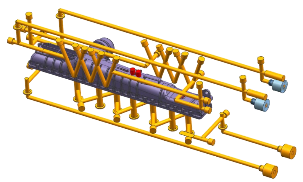
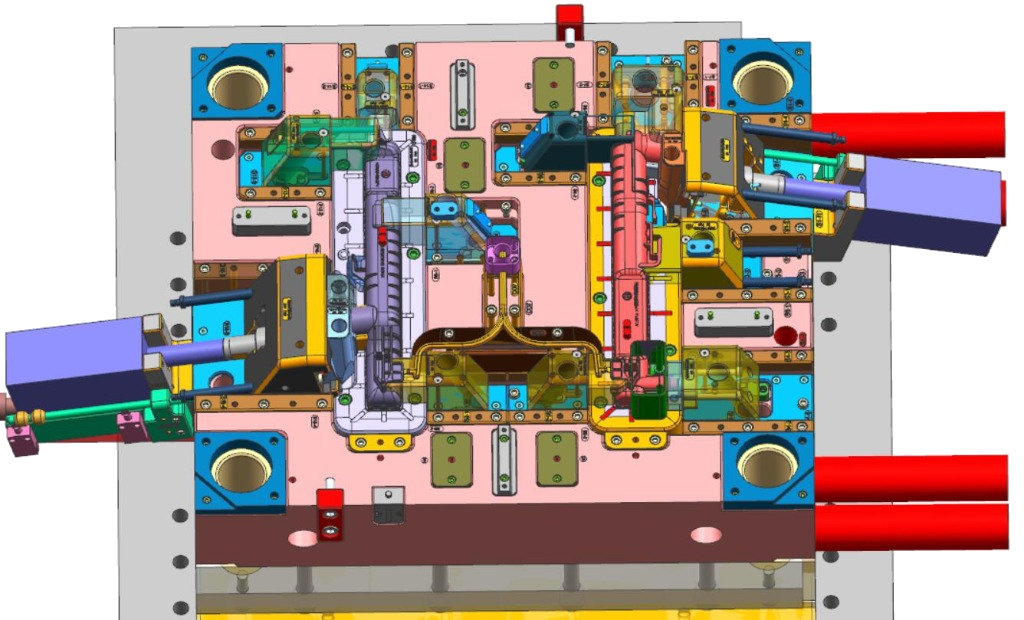
A robust mold layout determines cavity orientation, parting line location, runner system balance, and machine press compatibility before tool construction begins.
Cavity arrangementBalanced 1x1, 1x2, 2x2, 1x4, or 1x8 cavitation. Symmetrical H-pattern or radial runner layout ensures identical pressure drop and fill time across all cavities.
Parting surface (PL)Step and contoured parting lines designed along natural part edges to minimize flash, eliminate witness lines on cosmetic faces, and simplify CNC milling.
Press matchingClamping force calculated against total projected area and peak cavity pressure (30–65 MPa). Mold base footprint verified against tie-bar spacing and platen mounting holes.
Engineering Rule:Symmetrical runner balancing prevents short shots in outer cavities and over-packing in center cavities, directly eliminating part-to-part weight variance.
Melt Feed System
Gate Location & Gating Selection
Gate placement directly controls melt front velocity, weld line (knit line) positioning, packing efficiency, fiber orientation, and final cosmetic appearance.
Gate type selectionEdge gates, sub-gates (tunnel/banana gates for automatic degating), pinpoint gates (3-plate molds), or hot tip / valve gates to minimize gate vestige.
Location strategyGating into the thickest cross-section feeding toward thinner areas ensures continuous packing pressure and eliminates premature gate freeze-off.
Weld line controlPredicting melt confluence around openings and bosses so weld lines form in low-stress, hidden areas away from structural snap joints and screw bosses.
Uniform nominal wall thickness is essential for consistent heat dissipation, uniform shrinkage rates, and eliminating internal stress concentrations.
Nominal uniformityTargeting consistent nominal walls (typically 1.5–3.0 mm for ABS, PC, PC/ABS; 1.2–2.5 mm for PA66) throughout the entire molded component.
Wall transitionsSmooth thickness transitions with slopes not exceeding 3:1. Generous blending radii (R ≥ 0.5 × T) eliminate sharp notches and flow turbulence.
Rib & boss ratiosRib base thickness designed at 40% to 60% of nominal wall thickness with 0.5°–1.0° draft to prevent visible sink marks on cosmetic Class-A surfaces.
Engineering Rule:Coring out thick solid bosses and structural corners reduces injection cycle times by 20% to 35% and eliminates internal vacuum voids.
Release Geometry
Draft Angle Analysis & Texture Allowances
Adequate draft angles ensure clean separation from cavity and core steels without surface drag marks, scuffing, or high ejection force.
Cavity vs. core draftMinimum 0.5°–1.0° on polished cavity faces; 1.0°–1.5° on core faces ensuring the molded part reliably retains on the moving half upon tool open.
Texture allowanceAdditional 1.0° to 1.5° of draft angle per 0.025 mm (0.001 in) of grain depth (SPI / VDI 3400 / Mold-Tech MT texture standards) to prevent texture dragging.
Deep ribs & shut-offsInternal deep ribs drafted at 0.25°–0.5° per side. Kiss-off shut-off surfaces require minimum 3°–5° draft to prevent steel galling and flash formation.
Engineering Rule:Insufficient core draft causes parts to drag or stick on the stationary cavity half, interrupting automatic press cycles and damaging cosmetic surfaces.
Mechanical Action
Demolding & Undercut Release Solutions
Internal snaps, exterior lateral holes, and threaded features require specialized in-mold mechanical or hydraulic mechanisms to release undercuts without part distortion.
Ejection system layoutBalanced ejector pins, flat blade ejectors, stripper plates, and sleeve ejectors positioned directly beneath ribs and perimeter walls to avoid punch-through.
Internal liftersAngle lifters (typically 5°–12° travel angle) with guided base blocks to release internal snap clips and reverse ribs synchronized with ejector plate stroke.
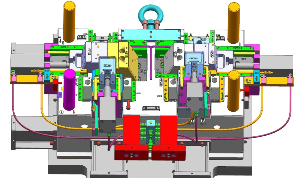
Side action slidersCam pin (angle pin) driven slide assemblies with hardened tool steel gibs, self-lubricating bronze wear plates, and positive heel block (wedge) locks.
Hydraulic & rotating coreHigh-torque hydraulic cylinders for long-stroke lateral cores; synchronized planetary gear drives for multi-cavity automatic internal thread unscrewing.
Engineering Rule:Positive mechanical wedge locks counter extreme cavity injection pressure, preventing slide push-back and zero-flash shut-off over millions of production cycles.
Mechanism Engineering
In-Mold Mechanism & Tool Architecture Showcase
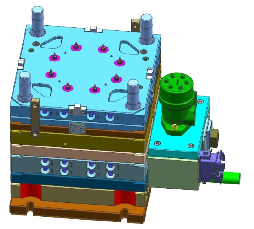
High-performance molds require more than standard cavities. Explore representative 3D CAD engineering for complex side actions, 3D conformal cooling networks, heavy-duty wedge locking, and multi-cavity automated gear unscrewing systems.
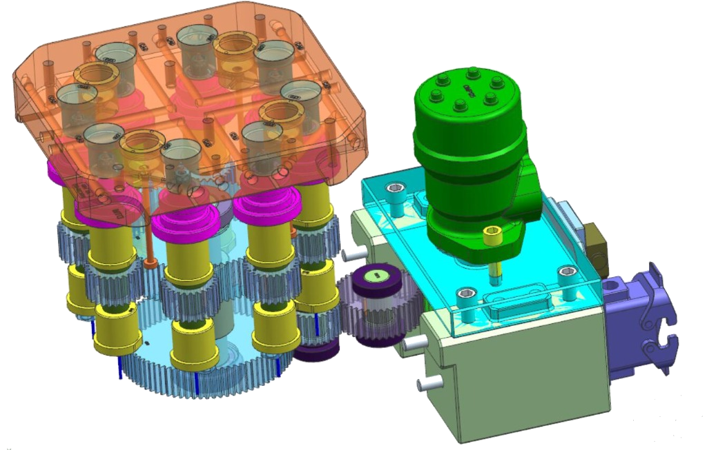
Eight-cavity synchronized gear train with integrated motor drive for continuous, flash-free internal thread demolding.
Transmission: Precision gear train with central driving gear and 8 synchronized planetary spindles
Drive system: High-torque electric or hydraulic gear motor delivering smooth, backlash-free rotation
Core cooling: Independent rotary water couplings providing direct internal chilling during unscrewing
Custom Mechanisms
Need Custom Slide, Lifter or Unscrewing Tooling?
Have a part with challenging undercuts, complex parting lines, or internal threads? Submit your 2D/3D part files for an early feasibility and DFM review.
Confidentiality Assurance: Visuals display non-proprietary engineering concepts for tooling architecture and mechanism feasibility. Client-specific CAD models, part drawings, and proprietary dimensions are protected under formal NDA agreements and exchanged via secure private channels.
Key dimensional proportions and tolerance guidelines applied during Nodinson's formal injection mold DFM reviews.
Design Parameter
Engineering Recommendation
Manufacturing & Quality Risk
Nominal Wall Thickness
1.5 – 3.0 mm (standard polymers)
Thick walls cause sink marks & long cycles; thin walls cause short shots.
Rib Thickness Ratio
40% – 60% of nominal wall (T)
Ribs > 60% T create visible sink depressions on opposite cosmetic faces.
Corner Blending Radii
Inside R ≥ 0.5 × T; Outside R ≥ 1.5 × T
Sharp internal corners concentrate stress and cause crack initiation.
Core Draft Angle
1.0° – 1.5° minimum
Inadequate core draft causes sticking, pin push-through, and part deformation.
Textured Surface Draft
Base draft + 1.0° per 0.025 mm texture depth
Insufficient texture draft causes unsightly drag stripes and white witness marks.
Shut-Off Angle
3° – 5° minimum between mold halves
Shallow shut-off angles (< 3°) cause steel galling, premature wear, and flash.
Venting Depth
0.015 – 0.025 mm (resin dependent)
Inadequate venting causes diesel effect (burn marks) and short shots.
Customer Deliverables
What You Receive in a Nodinson DFM Report
Every tooling project is preceded by a structured engineering report. We review drawing revisions, identify design concerns, and propose optimized 3D geometry before order confirmation.
3D Draft Angle Gradient MapColor-coded 3D CAD visualization identifying zero-draft faces, insufficient draft areas, and undercut regions.
Wall Thickness Cross-SectioningDetailed volumetric thickness analysis highlighting heavy mass concentrations, sink risks, and flow bottlenecks.
Parting Line & Shut-Off ProposalPrecise 3D parting surface layout with core/cavity boundary splits, shut-off angles, and stepped interlock details.
Gate & Runner System ProposalGate type, orifice dimension, runner layout, and predicted knit line / air trap confluence zones.
Ejector Pin & Witness Mark ReviewPin location layout, blade/sleeve selections, and expected witness marks on non-cosmetic part surfaces.
Side Action & Lifter EnvelopesMechanical slider travel distances, lifter stroke clearance, and positive heel block locking configurations.
Request a Confidential DFM Review for Your 3D CAD
Share your STEP/IGES model, target resin, and annual production volumes. We execute non-disclosure agreements (NDA) prior to CAD transmission.

 Full Tool AssemblyInspect 3D CAD