Draft and release
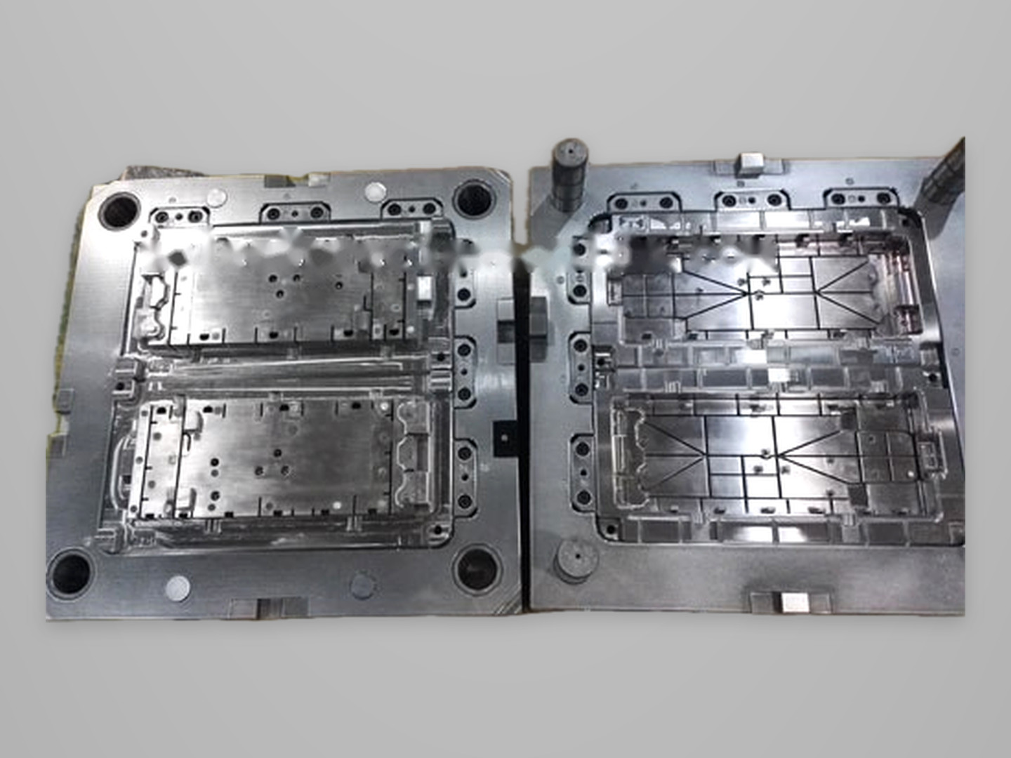
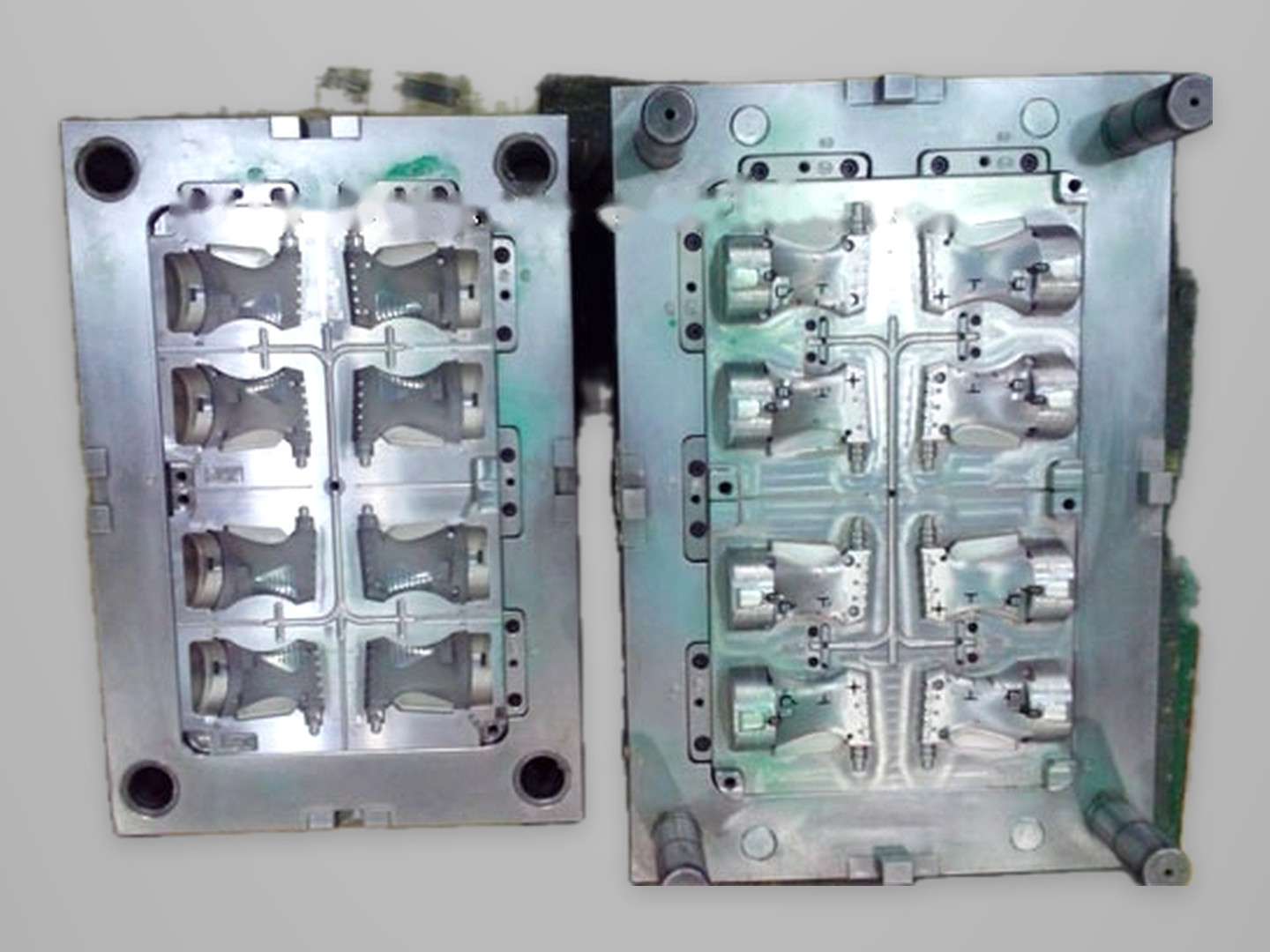
Review draw direction, draft, shutoffs and undercuts. A proposed change is discussed against the appearance and functional surfaces the customer needs.
Tooling for electronic, instrument and industrial equipment components starts with an agreed part design and ends with a defined acceptance and delivery scope. We discuss draft, wall thickness and demolding early so the tool design follows the part's real requirements.
A design review should connect product intent to how the part releases from the mold and how it will be inspected.
Review draw direction, draft, shutoffs and undercuts. A proposed change is discussed against the appearance and functional surfaces the customer needs.
Examine transitions, ribs, bosses and likely sink or warp risks. Resin grade, geometry and appearance requirements all affect the recommendation.
Record the drawing revision, issue, suggested 3D change and customer decision. Complete design files are exchanged by an agreed channel after NDA when required.
A view of the engineering office and a CNC operation.


High-performance molds require more than standard cavities. Explore representative 3D CAD engineering for complex side actions, 3D conformal cooling networks, heavy-duty wedge locking, and multi-cavity automated gear unscrewing systems.
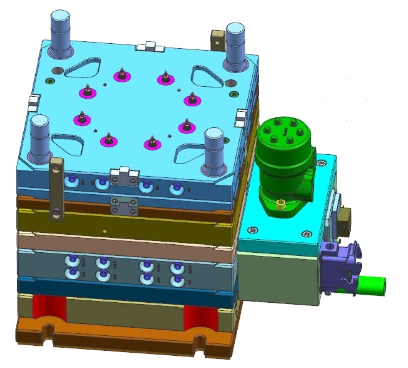 Full Tool AssemblyInspect 3D CAD
Complete multi-plate mold base with standardized European / DME alignment, quick-connect water manifolds, and integrated side-drive housing.
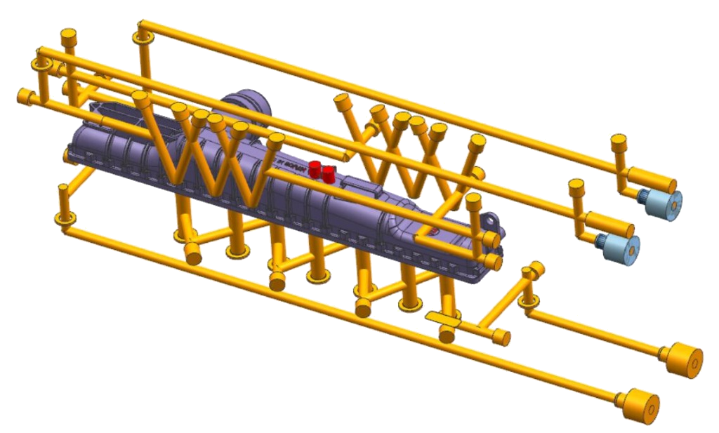 Thermal BalanceInspect 3D CAD
Contoured 3D cooling circuit design wrapped closely around deep structural ribs and wall transitions for maximum thermal equilibrium.
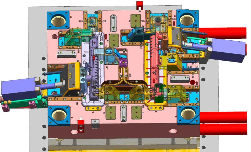 Complex UndercutsInspect 3D CAD
Dual-cavity layout featuring multi-angle hydraulic slide cylinders, mechanical lifters, and precision parting shut-offs.
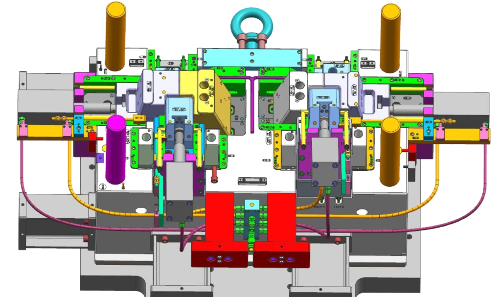 Safety & LockingInspect 3D CAD
Solid alloy steel wedge locks (heel blocks) countering intense injection pressure, backed by in-mold stroke sensor feedback.
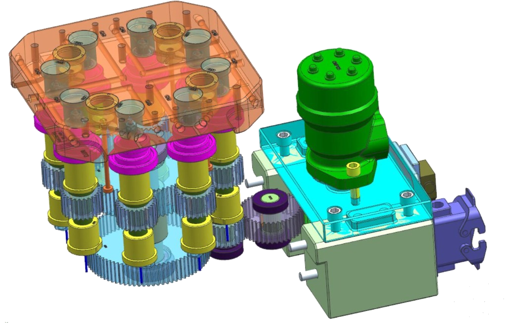 Rotating DemoldingInspect 3D CAD
Eight-cavity synchronized gear train with integrated motor drive for continuous, flash-free internal thread demolding.
Have a part with challenging undercuts, complex parting lines, or internal threads? Submit your 2D/3D part files for an early feasibility and DFM review.
The order below keeps the formal DFM stage after quotation and order confirmation. Trial scope, moldflow and FAT are set by the project agreement.
Set the NDA parties, scope and exchange method before sharing sensitive drawings.
Customer checkpoint: Confirm the NDA terms and which files may be exchanged.Use the drawing revision, material, expected quantity and delivery needs to define a quotation scope. An early feasibility discussion may identify open questions.
Customer checkpoint: Confirm the files, critical features and quotation assumptions.Agree technical scope and commercial terms before formal engineering work starts.
Customer checkpoint: Approve the quotation and written order.Review draft, wall thickness, demolding direction, undercuts and likely part or tool risks; propose changes to the part 3D design where useful.
Customer checkpoint: Review the issue list and approve any design changes.Use filling or cooling analysis when the geometry and project risks justify it. The analysis scope is agreed for each job.
Customer checkpoint: Confirm whether to run the study and review its conclusions.Develop the agreed 3D and 2D tool design and bill of materials, including interfaces and planned construction.
Customer checkpoint: Approve the design package and any specified press interface.Depending on tool design: cooling-channel work, CNC roughing, heat treatment, electrodes, CNC finishing, EDM, fitting, polishing or texturing. Sequence and methods vary by steel, structure and finish.
Customer checkpoint: Review changes that affect the approved scope.Run the agreed trial, inspect samples against agreed features, and carry out FAT only when its scope and method are specified.
Customer checkpoint: Review trial records, samples and agreed inspection results.Record feedback, make agreed tool or process changes and submit revised samples as needed.
Customer checkpoint: Approve the sample revision and any remaining actions.Present a pre-shipment mold checklist for approval, then package the tool and arrange the agreed air or sea shipment.
Customer checkpoint: Approve the checklist, packing and delivery documents.For a tool export order, sample approval leads to mold acceptance, packaging and shipment. For a continuing plastic-part order, the approved sample can instead lead into agreed production, inspection and part delivery. The two delivery scopes should be stated separately in the quotation.
Explore related catalog parts. Images illustrate part types; confirm materials, dimensions and acceptance requirements for your project.
No. We agree whether filling or cooling analysis is useful and define its scope for the part and tool before treating it as a project deliverable.
Yes. The DFM discussion identifies the drawing revision, manufacturing concern and proposed change; the customer decides which changes are accepted before the tool design proceeds.
Provide target press information and interface drawings. Locating, ejection, cooling and electrical connections are selected against the approved mold design, not assumed to be interchangeable.
Public images can be saved or captured, so sensitive CAD, dimensions and BOM files are exchanged after an NDA through an agreed channel rather than displayed openly.
Share the application, drawing revision, material requirements, expected quantity and acceptance needs. Sensitive files can be exchanged after an NDA through a channel we agree together.
Request a Quote